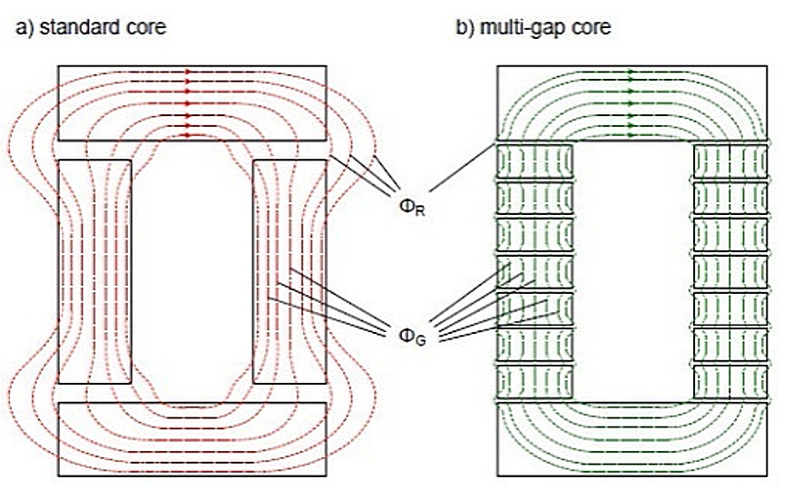
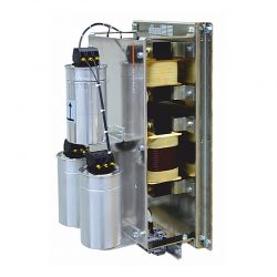
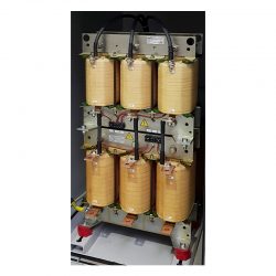
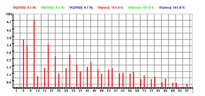
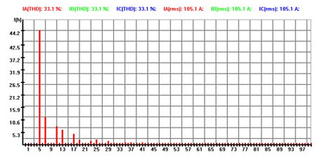
In the design and manufacturer of series harmonic filters, the laminated magnetic core, around which the coils are wound is of crucial importance. The linearity of the filter’s magnetic characteristics is paramount. Any non-linearity can result in increased power losses (and associated temperature rise) and an increase in audible noise, especially in the areas adjacent in the air gaps.
The design of the magnetic cores allows for a constant value of inductance irrespective of a wide range of changes in the filter current (magnetic linearity), reducing the audible noise level generated and eliminating the external magnetic field (see diagram). Consequently, the additional losses in the core, winding and structural elements are all reduced. The result is the series passive harmonic filters and other products are more efficient, have less power losses, lower operating temperatures and reduced audible noise compared to competitors.
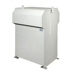
SPQ-EF3H Series Harmonic Filters
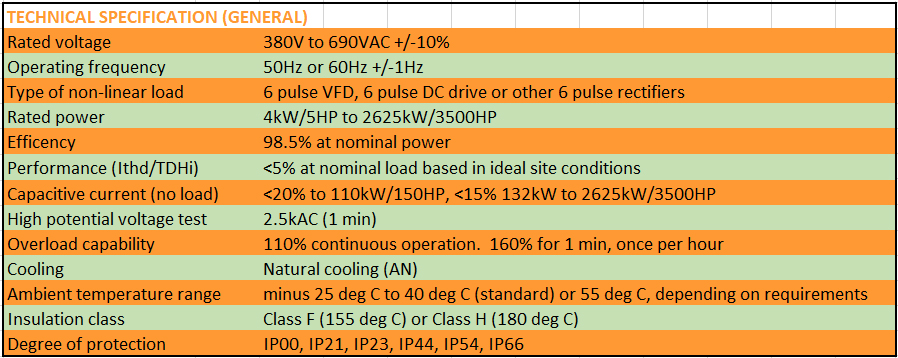
The standard range is 4kW/5HP to 2625kW/3500HP in voltages from 380V to 690V, 50Hz or 60Hz, in enclosures IP00, IP20, IP23, IP54 and IP66 and ambient temperatures to 55 deg C. General specification is shown.
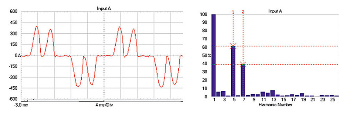
SPQ-EF3H harmonic filters are highly efficient with performance levels of <5% Ithd. Another important feature is the capacitive current at no-load being <15%. This ensures capacitor bank disconnection is not required at no or light loads.
Typical performance of SPQ-EF3H series passive harmonic filter on 110kW VFD:
Harmonic filters for panel builders and retrofits (to 110kW)
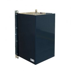
We have collectively introduced the innovative SPQ-EF3H three phase harmonic filter design for the hanging vertical position. This is ideal for retrofits (can be mounted on the wall) and for electrical panel builders as it can be installed inside a panel or switchboard thus saving valuable floor space.
Range is from 4kW/5HP to 110kW/150HP in IP00 and IP20 formats. Higher IP ratings available on request.
For dimensions of EF3H IP21 harmonic filters please click here.
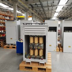
SPQ-EF3H series harmonic filters (from 110kW/200HP to 2625kW/3500HP)
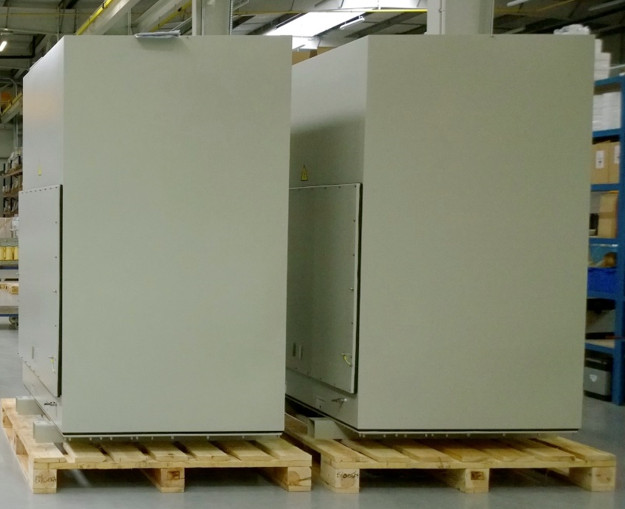
For applications above 110kW, wall mounting series harmonic filters are not available. Traditional floor mounted versions are therefore offered in powers to 2625kW/3500HP for AC VFD, DC SCR drive and other rectifier applications.
Specification as per advised with <5% Ithd performance, <20% kVAr to 110kW. Above 110kW, <15% kVAr at no load. Operation up to 55 deg C. The range of enclosure options from IP00 to IP66.
Special marine and offshore rated designs are available, encompassing thermal reactor monitoring, capacitor protection and if required, PQ (power quality) monitoring can be provided. Marine deck proof enclosures to IP66 also available.
Please note that du/dt and sinewave output filters applications match the range 4kW to 2625kW VFD kVA are available. For more information click here.
For all your passive series harmonic filters (and sinewave filters) enquiries and applications please contact us.
Enclosure options
There are a number of harmonic filter enclosure options (IP00 to IP66), this combined with two hundred and eighty (280) harmonic filter variants spread over seven voltage/frequency ranges, means It is not feasible or possible to detail all the dimensions and nett weight information on this website.
For information on dimensions of any harmonic or sinus filters please contact us.
RiteSineLab harmonic estimation software
Harmonic estimation software is now available to model drive applications using up to ten (10) nodes for AC and DC drives AND programmable current sources. The full range of series passive harmonic filters can also be selected for harmonic mitigation simulation. The programme automatically selects the appropriate filter from the designated database.
The harmonic voltage and currents are modelled to the 50th order (for standards compliance) and also up to 100th order. The Urms and Irms waveforms and associated spectra is available for each node.
Please contact enquiries@harmonicsolutions-marine.com for more information.
An example of RiteSineLab harmonic modelling a single line diagram (with 3% AC line reactors in each VFD; 4% in the DC SCR drive) is illustrated :
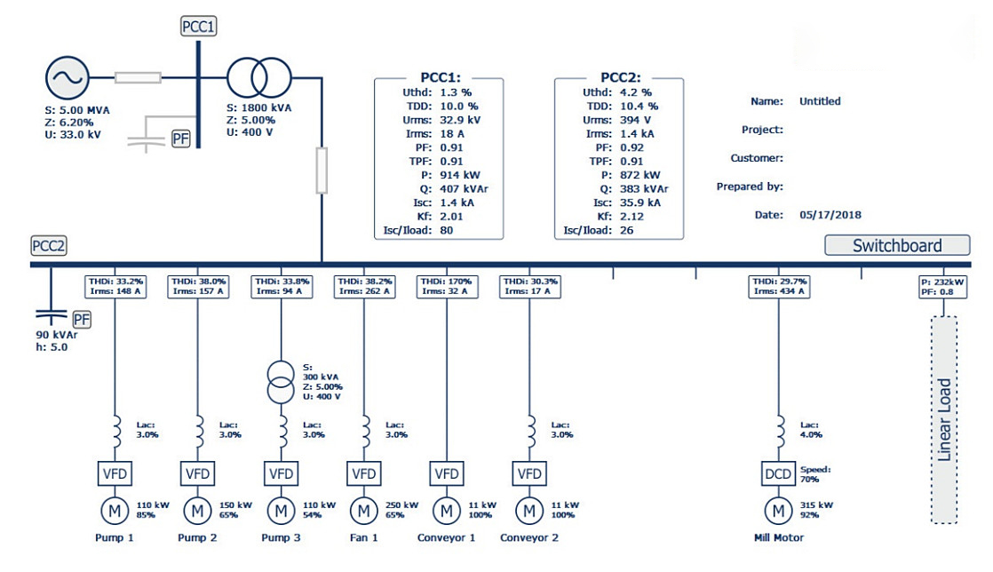
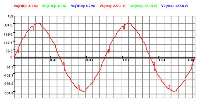
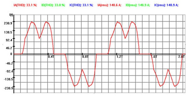
Example of line voltage and phase current waveforms (all three waveforms can be displayed) for Phase one, Node 1 (LHS). Note that the line notching is due to the DC drive connected to Node 9:
Comprehensive reports in pdf form will be downloadable including compliance or otherwise with IEEE 519 (1992), IEEE 519 (2014) and other standards.

